Produktberatung
Ihre E -Mail -Adresse wird nicht veröffentlicht. Erforderliche Felder sind markiert *

If you have ever stood beside a crane or a lift platform and wondered how much load a cylinder can really move, the answer comes down to one relationship: the pressure of the oil multiplied by the area it pushes against. That is the heart of every hydraulic cylinder force calculation, and after a few repetitions it becomes second nature.
We build cylinders for cranes, aerial work platforms, tow trucks and piling rigs, so a good part of our week is spent on this arithmetic. Below is the method we actually use, a worked example in both metric and imperial units, and the small details that decide whether the number on paper matches the number on site.
Every calculation begins with F = P × A, where force is measured in newtons (or pounds-force), pressure in pascals (or psi) and area in square metres (or square inches). The only real work is finding the correct area, because a double acting cylinder presents two different ones depending on which way the oil is flowing.
When oil enters the cap end, it acts on the full face of the piston. For a bore diameter D, the area is A = π × D² ÷ 4. Multiply that by the working pressure and you have the extension force.
When oil enters the rod end, the rod itself occupies part of the piston face. If the rod diameter is d, the effective area becomes A = π × (D² − d²) ÷ 4. Because the rod always removes area, retraction force is always lower than extension force, often by 30 to 45 percent on a typical rod-to-bore ratio.
Keep the units consistent. Mixing bar with square inches is the single most common source of nonsense results, and a spreadsheet will happily return a confident, wrong answer without warning you.
Suppose a double acting cylinder has a 100 mm bore, a 70 mm rod and a working pressure of 200 bar.
In tonnes of force that is roughly 16 tonnes pushing and 8 tonnes pulling, a difference large enough to change how a machine is specified. The same cylinder described in imperial terms, a 4 inch bore and 2 inch rod at 2,500 psi, gives about 31,400 lbf extending and 23,560 lbf retracting. The ratio stays identical, which is a handy sanity check when you are moving between drawing sets.
| Example | Bore | Rod | Pressure | Extension Force | Retraction Force |
|---|---|---|---|---|---|
| Metric | 100 mm | 70 mm | 200 bar | 157 kN | 80 kN |
| Imperial | 4.0 in | 2.0 in | 2,500 psi | 31,400 lbf | 23,560 lbf |
The calculation is only as good as its inputs, and three of them cause most of the errors we see:
If you only know the relief setting, run the calculation with that value to find the maximum force the cylinder can generate, then repeat it with the typical working pressure to see what the machine uses in daily duty. The gap between the two often explains why a machine feels overbuilt in one function and marginal in another.
Site language runs on tonnes rather than kilonewtons. To convert, divide newtons by 9,810, since one metric tonne-force equals 9.81 kN. The 157 kN above becomes about 16 tonnes, which is a figure most operators can picture immediately.
| Quantity | From | To | Multiply By |
|---|---|---|---|
| Pressure | 1 bar | psi | 14.50 |
| Pressure | 1 MPa | bar | 10 |
| Pressure | 1 psi | bar | 0.0689 |
| Force | 1 kN | lbf | 224.8 |
| Force | 1 metric tonne-force | kN | 9.81 |
| Force | 1 US ton-force | kN | 8.90 |
| Length | 1 inch | mm | 25.4 |
Watch which tonne you are using. A US ton is 2,000 lbf while a metric tonne is 2,205 lbf, and that ten percent difference has a way of surfacing at exactly the wrong moment.
The formula describes an ideal cylinder. Real hardware loses a little, and understanding where it goes helps you judge how much margin to add.
Piston seals, rod seals and guide rings all resist motion. Worn or over-tight seals push this figure up, and a cylinder that has been sitting unused for months often breaks away at a noticeably higher pressure than it needs to keep moving.
Oil leaving the opposite chamber has to travel through hoses, valves and filters. That restriction creates back pressure which opposes the motion, so the net force is the working pressure force minus the return-side force.
A cylinder pushed off-axis bends slightly, the rod binds in the guide, and friction climbs sharply. This is a mechanical problem rather than a hydraulic one, and no amount of extra pressure fixes it cleanly.
As a planning allowance, expect 5 to 15 percent below the theoretical value. For anything safety-related, treat the calculated number as a ceiling rather than a guarantee.
Once you have a realistic force figure, the next decision is how much margin to carry. There is no universal answer, but these starting points work well in mobile machinery:
A generous safety factor is not free. It adds weight, cost and heat, so the aim is a number that reflects the real duty rather than a reflex. That is also why we ask customers for the duty cycle alongside the pressure and bore.
Knowing the required force is only the start. The cylinder then has to deliver it across thousands of cycles, in dust, rain and temperature swings, without the rod bowing or the seals weeping.
On a truck-mounted crane, for instance, the luffing force changes continuously as the boom angle rises, and the worst case usually arrives at a low angle with a full load. Sizing to the average would leave the machine short exactly when it matters.
 Truck-Mounted Crane Hydraulic Luffing CylinderAdjusts boom angle for lifting at varying heights and distances; dual-cylinder option supports heavier loads, with sizing considerations for changing luffing forces.View Product →
Scissor lifts bring a different twist: several lifting cylinders share the load, and the force required per cylinder is highest when the platform sits at the bottom of its travel and the linkage angle is least favourable. These are the sort of details that sit behind the design considerations for a specific application, and they are worth checking before the bore is fixed.
 Scissor Lift Aerial Platform Hydraulic Lifting CylinderSingle-acting cylinders raise and lower the platform with damping holes for smooth positioning; multiple cylinders share load, making worst-case linkage force worth checking.View Product →
Pipe jacking is a good example of a job where the simple formula is only the beginning. The main jacking cylinders push a whole string of pipe through the ground, so the required force has to cover friction along the entire string, soil resistance at the face and the weight of the pipe itself. The calculation is still pressure times area, but the area has to be large and the pressure has to be available continuously over a long stroke.
 Pipe Jacking Machine Hydraulic Main Jacking CylinderCore power source for pipe jacking, providing strong thrust and precise extension; force sizing must cover friction along the pipe string and face resistance.View Product →
In cases like this, the cylinder is designed around the load rather than selected from a catalogue, and the force figure becomes the first line of a specification instead of the final answer.
Force calculations are one of those small skills that repay the effort many times over. Once you can move confidently between pressure, area and tonnage, you can sanity-check a supplier's drawing in a few minutes, spot an undersized cylinder before it reaches the machine, and explain to a customer why the pull force is not the same as the push force.
If you would like a second pair of eyes on a calculation, send us the bore, rod diameter, pressure and a sketch of the mounting. We are always glad to talk through the numbers before anything is manufactured.
Ihre E -Mail -Adresse wird nicht veröffentlicht. Erforderliche Felder sind markiert *
Das wunderbare Design trifft auf die strenge Fertigung
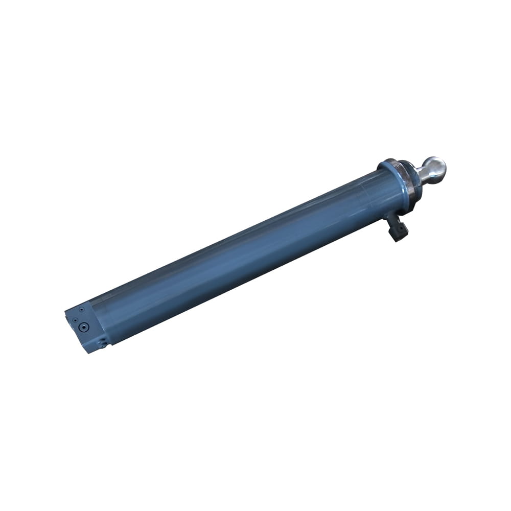 Scherenlift -Luftplattform hydraulischer Auslegerzylinder
Funktion: Unterstützt das Fahrzeug fest: Gewährleistung der Stabilität während des Betriebs. Der Ballkopffuß wird automatisch auf Hängen ausgeführt, während ...
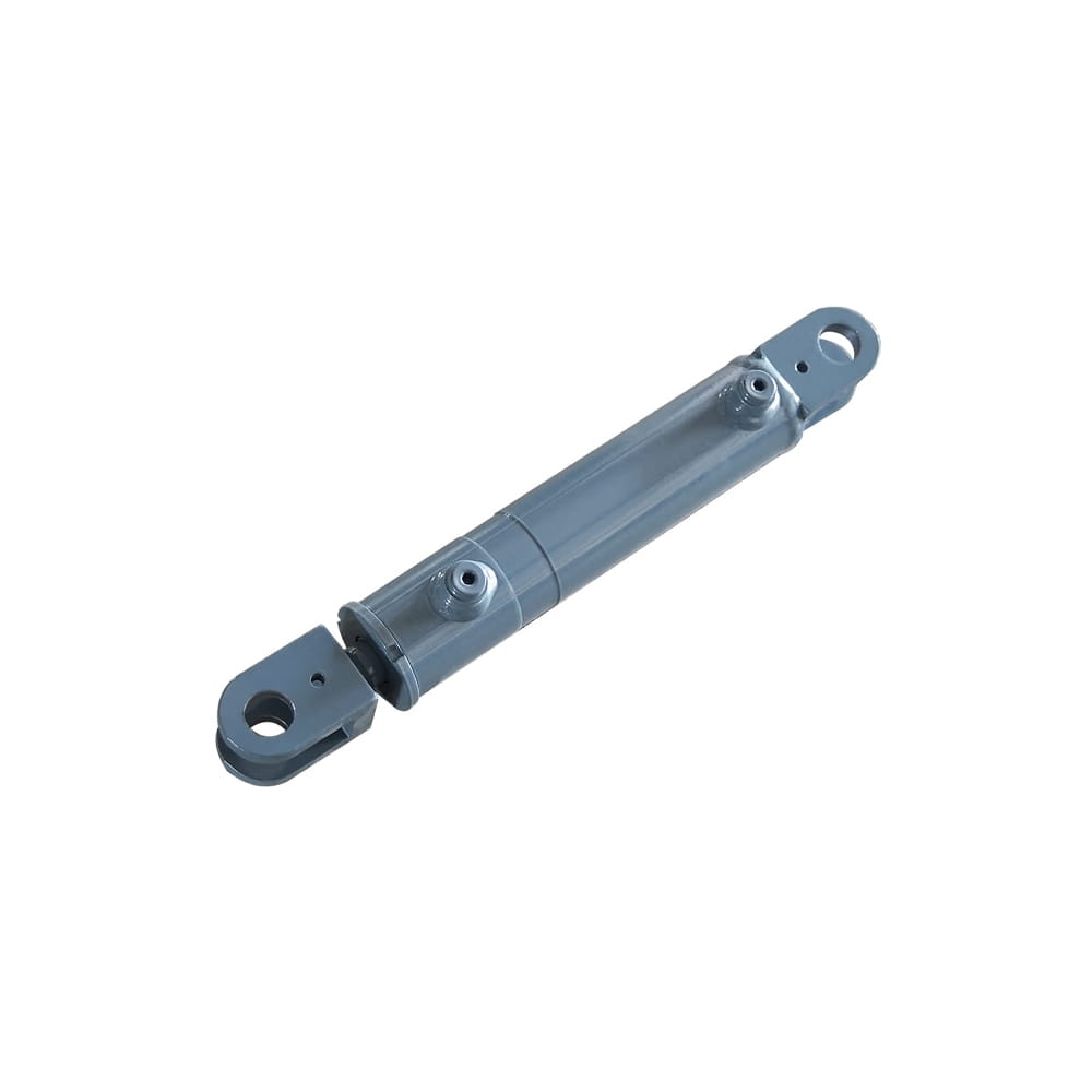 Hydrauliklenkzylinder der Schere Lift Luftplattform
Funktion: Anschließen des Chassis und der Radnabe: Durch den hydraulischen Druck fährt die Kolbenstange zum Bewegen und ermöglicht eine präzise Radnabendrehu...
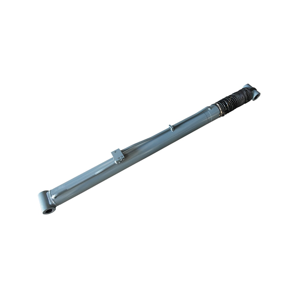 Boom Lift Luftplattform hydraulischer Luffzylinder
Funktion: Passen Sie den Winkel des teleskopischen Arms an, um die Arbeitsplattform in verschiedenen Höhen und Positionen flexibel zu positionieren, und erfü...
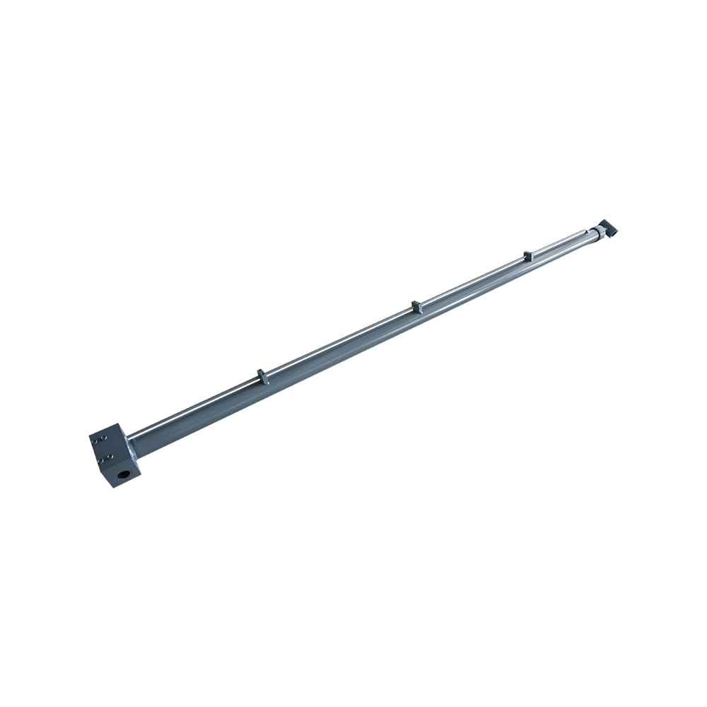 Auslegerlift -Luftplattform hydraulischer Teleskopzylinder
Funktion: Passen Sie die Länge des Arms an, damit die Luftarbeitplattform flexibel anheben und sich bewegen kann, um den Bereich und die Höhenanforderungen z...
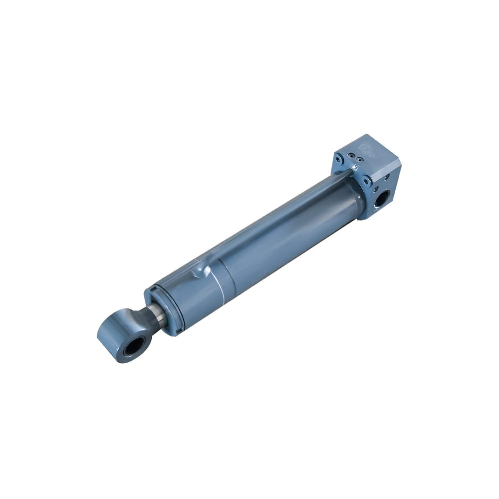 Boom Lift Luftplattform Hydraulikrahmen -Rahmenzylinder
Funktion: Passen Sie das Chassis automatisch am unteren Rand der Plattform an einen ebenen Zustand an und gewährleisten eine stabile und wackelfreie Unterstü...
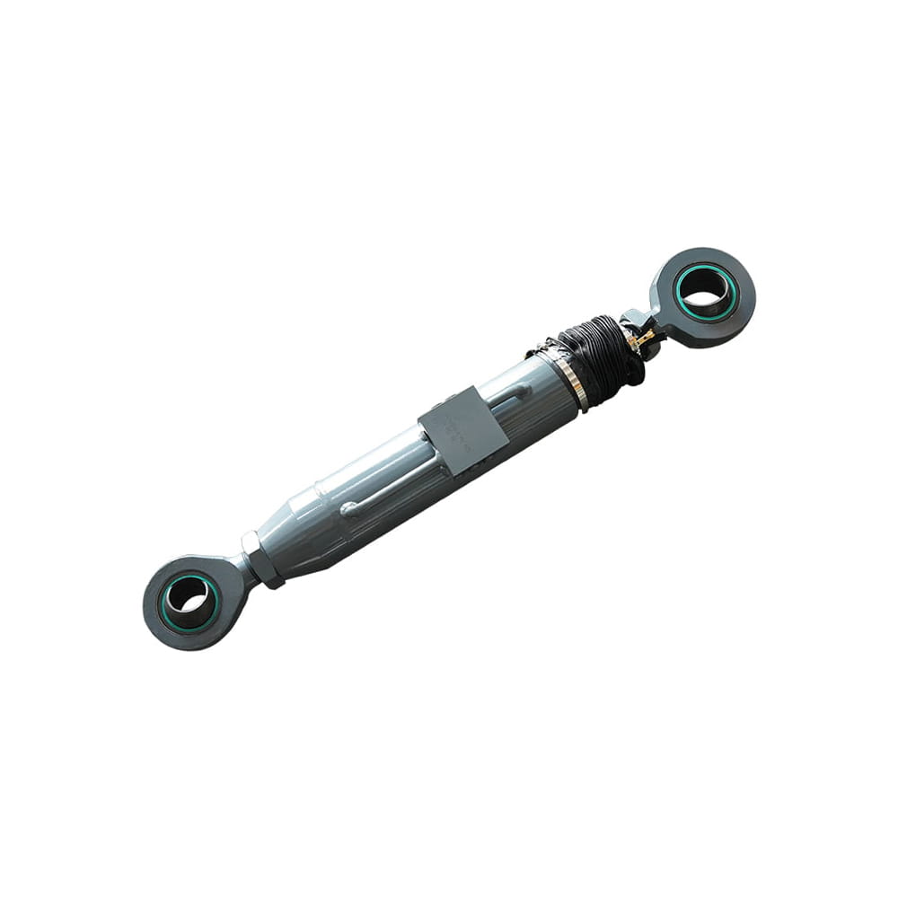 Boom Lift Aerial Platform Hydraulic Bridge Extension Zylinder
Funktion: Ein wichtiges Design, das die Anpassungsfähigkeit und den Arbeitsbereich verbessert. Diese Funktion ermöglicht es der Plattform, ihr Chassis unter ...
Copyright © by Zhejiang Huanfeng Machinery Co., Ltd. Rights Reserved.
